Get an estimate on delivery to your location.
- Pay by card, bank transfer or USSD at checkout
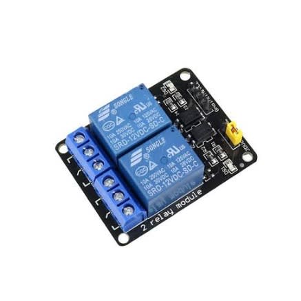
This module contians two relays that are electrically isolated from the controlling input. The relays can be used to switch higher voltage and current loads than a microcontroller can traditionally accomplish.
The relay has two outputs-normally open and normally closed (NO and NC). When the IN1 or IN2 pin is connected to ground, NO will be open and NC will be closed, and when IN1 or IN2 is not connected to ground the opposite occurs. Connecting a circuit or device between one of these two pins, the common pin on the relay output, and a power source will allow you to toggle power to a circuit or device.
- Connect an LED and 220 ohm resistor in series between the NO pin (the right pin) on the terminal block on one of the relays and ground, then connect a 12V power source to the common pin (the left pin) on one of the relays. Nothing will happen (yet).
- Next connect a toggle switch or button between ground and one of the middle two pins on the header strip on the relay module. The middle-left one corresponds to the left relay, and the middle-right one corresponds to the right relay. Connect the rightmost pin to 5V and the leftmost pin to ground.
- When the switch is flipped or the button is pressed, either IN1 or IN2 will become connected to ground. The relay should make a loud click and the LED should turn on. A microcontroller can also be used to control IN1 and/or IN2 and cause the relay to trip.
Warning:
HIGH VOLTAGE IS DANGEROUS. If you are using this module to control high voltages like something connected to a wall socket, please exercise caution.